Activity Name:
Digestive System Exploration - it’s lit.
Grade Level:
7th grade (Could work for 9th - 12th)
Time Required:
240 minutes
Expendable Cost:
- Tape - $15
- Foamboard/Cardboard - Free up to $15
- 22gauge solid hookup wire - $16.95
- 2 Alka seltzer tablets - $0.44/2 tablets
- 2 Plastic cups - $0.20/2 cups
Group Size:
4 students (Can work with groups of 6 to save material cost)
Subject area:
biology, life science
Summary:
We all have heard of proteins, fats and carbohydrates, but how do we actually extract these from our turkey sandwich? Students will learn about the digestive system and how it helps break down all of the various foods we eat into usable molecules! Using different colored LEDs and hand drawn pictures, they will create diagrams of the digestive system that help display where each molecule is broken down.
Keywords:
digestive system, 3D digestive system, modeling, nutrition, life science, Arduino
Educational Standards:
ISTE
- Innovative Designer
- Students use a variety of technologies within a design process to identify and solve problems by creating new, useful or imaginative solutions.
- Computational Thinker
- Students develop and employ strategies for understanding and solving problems in ways that leverage the power of technological methods to develop and test solutions.
- Creative Communicator
- Students communicate clearly and express themselves creatively for a variety of purposes using the platforms, tools, styles, formats and digital media appropriate to their goals.
NGSS
- MS-LS1-3
- Use argument supported by evidence for how the body is a system of interacting subsystems composed of groups of cells.
- MS-LS1-7
- Develop a model to describe how food is rearranged through chemical reactions forming new molecules that support growth and/or release energy as this matter moves through an organism.
- HS-LS1-7
- Use a model to illustrate that cellular respiration is a chemical process whereby the bonds of food molecules and oxygen molecules are broken and the bonds in new compounds are formed, resulting in a net transfer of energy.
Prerequisite Knowledge:
The basics of Arduino, how to code a SparkFun RedBoard, the anatomy of an LED
Learning Objectives:
- Identify all organs that assist in the digestive system
- Identify what chemical reactions and enzymes are responsible for the breakdown of proteins, fats, and carbohydrates
- The body is a system of multiple interactive subsystems
Materials List:
- For introduction demo
- 2 alka seltzer tablets, (1 broken up into small pieces or a fine powder and 1 whole tablet) in separate small clear plastic wine glasses
- 2 clear cups of water
- 1 piece of foamboard or cardboard roughly (18”x24”)
- 1 SparkFun RedBoard and Breadboard
- 1 SparkFun RedBoard USB cable
- A laptop or computer with Arduino IDE installed
- 1 micro servo motor
- 4 jumper wires (1 red, 1 white, 2 black)
- 14 pieces of solid gauge hookup wire (12-16”)
- Recommended that you use only 2 colors, 7 of each color and that 1 of the colors be black.
- 1 pairs of wire strippers
- 1 roll of clear or masking tape
- 7 resistors (330 ohms)
- 7 LEDs, 2 red, 3 yellow, 2 green
- Starter code
- Full code
Introduction / Motivation:
Today, we are going to start a project that involves food! I bet that got your attention! More specifically, we are going to talk about how food is broken down by the body. Most of us are familiar with the terms “carbohydrates, proteins and fats”. These are the main things that constitute food, with some minerals and vitamins as well. We know that we need things like carbohydrates for energy, and proteins to help our muscles grow, and fats for brain health and other functions, but does anybody know how our body actually extracts these molecules from food? (Answers may vary between “in our mouth!” to “it turns it into poop!” Be prepared.)
All of this is part of a process called “Digestion”. (Write the word up on the board) Digestion consists of two sub-processes. One is “Physical” (Write this word up) which includes when we chew our food. Can anybody guess the second one? (Answer might be “digesting” or “extracting”. Looking for “Chemical”) Yes, “Chemical!” (Write the word up). The physical portions of our digestion are pretty simple! We chew our food so that it is easier to swallow, yes, but we also chew food so that the Chemical process is faster!
Think of it this way, (Get water cups out and place on a table where all can see), I have two forms of Alka Seltzer (show wine glasses of the Alka Seltzer), one is crushed up and one is a whole tablet. I want you to all watch as I pour these into separate glasses. First we will observe, then we will hypothesize. I want you to determine which one will dissolve faster (Pour the alka seltzer in, let each one finish bubbling.) So which one was it? (All should answer the crushed up/powdered form) Yes! That’s correct. Our body does the same thing. When we chew our food, we increase the “surface area” which is how much of the food is exposed to our stomach acid and other things, so it will digest faster. And our stomach actually does this weird act of compressing and squeezing to help crush the food into smaller parts. This is also an example of physical digestion.
We also need to know which organs in our bodies are responsible for aiding in our chemical digestion. We need to communicate this information in a way that is easy to understand. If you think of a museum exhibit, there is often a lot of Engineering and Design that goes into communicating information in a simple way. This will be your challenge: To communicate which molecules are broken down in each organ that aids in digestion.
Procedure:
Background
You should be familiar with how to splice wires yourself using the NASA method. This is a tough skill to learn and should be practiced on a few different wires to learn the method. In addition, familiarity with for loops is highly suggested as almost every event uses a for loop. Be aware of common mistakes that students make when using for loops.
Before the Activity
- For introduction demo
- Break 1 alka seltzer tablet into small pieces/crush it up slightly. Put in small plastic wine glass. Put the other whole tablet in a different small plastic wine glass.
- Fill up two clear cups with water
- Pull up video on how to splice wire to NASA standards
- Pull up video of demo of display so they understand what they are making
- Gather materials and make a kit for each group before hand
- Cut 56 pieces of solid gauge hookup wire (roughly 6”ish) per piece but doesn't need to be measured. These will be used for the NASA Splice practice, not for splicing the LEDs. Each student will get a pair of wires (planning for a class of 28)
With the Students
- Divide students into groups of 4 and give them their supplies. (Refer to the materials list.)
- Tell students that before we start coding and hooking up all of our LEDs, we first must learn a new skill - how to splice wires to LEDs to extend them.
- Show NASA Video. Once video is done, tell students that they will not be using solder as we do not need our wires to hold tension, but they will use some basic masking/clear tape to cover connections.
- Post the NASA link to either Google Classroom or email to students so they can watch this video again and follow it on their own. Handout scrap pieces of wire and let students practice on these.
- Next, we will need to do the NASA splice not between two wires, but between a wire and a LED. We need to splice these wires to the legs of the LED and adhere to a strict code so we all know which wire means what.
- Write up on the board the two colors. If using black, as recommended, we will start with that. Announce to the class that the black wire, or whatever color you chose, will always go to the short leg of the LED and therefore be the negative in our circuit. (Write up on the board "Black = short leg") And the other color that you chose will always go to the long leg and therefore be the positive. (Write up on the board “= long leg” next to the other color)
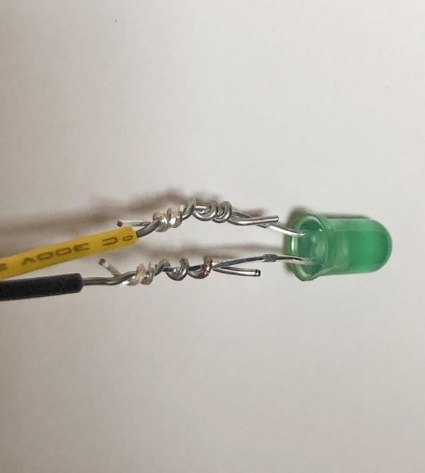
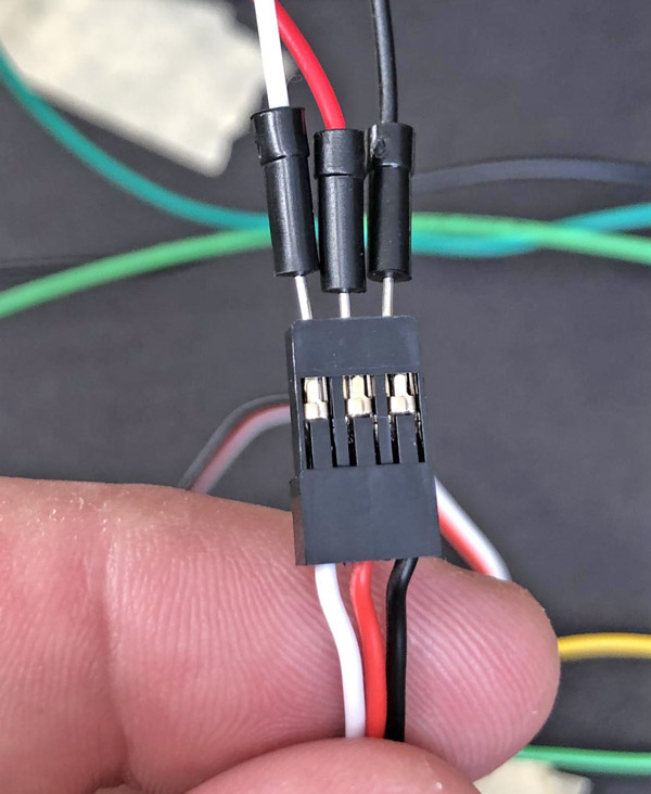
- Show Fig 1 to the students of how their LEDs should look when they finish splicing them.
- Students should now splice their LEDs, ideally each group member would splice at least 1, with 3 others splicing two. This is a great skill for all to have.
- Once all LEDs are spliced, have them check that they followed the color code for each before starting the next step. This will probably be the end of class 1.
Class 2:
- Students need to learn which molecules are broken down by particular organs in order to create an accurate display. I recommend lecture style while drawing a diagram of the digestive system on the board. Of particular importance are the mouth, the stomach, the liver + gallbladder and the pancreas. The small intestines should also be included, although they don't secrete any enzymes. Inform the students of each organ and what it breaks down. For brevity, I will summarize here. You may write this on the board or choose to let students research this and check with you.
- Mouth - Carbohydrates and Fats
- Stomach - Proteins
- Gallbladder - Fats
- Pancreas - All three!
- Next, students need to start planning out their physical build. List on the board the following color codes:
- Red - Proteins
- Green - Carbohydrates
- Yellow - Fats
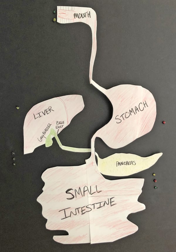
- Students must draw a representation of the organs and the digestive system similar to what you drew on the board, but each organ should be drawn on a separate piece of paper to then cut out and place on their foamboard/cardboard. I strongly recommend against letting them draw directly on the foamboard/cardboard as if they make an error, it is much tougher to fix.
- Next, students must begin to place their cutouts of the organs on their board to make one cohesive digestive system.
- Lastly, students will need to mark holes for the LEDs around the various organs. Refer them to their research or the table you wrote on the board. For instance, wherever their cutout for the “Mouth” organ will go, they should mark two LED holes. I recommend each be spaced out at least 15mm from one another to allow the wires enough room. I also recommend they write out what color/molecule will be next to each organ. So going back to the “Mouth” organ example. They should mark 2 LEDs, one for Carbohydrates and one for Fats next to where the cutout will be placed. Next to the stomach, there should only be 1 LED marked, red for protein. Next to the liver, there should be 1 LED marked for Fats. Next to the Pancreas there should be 3 LEDs marked, yellow, red and green as the Pancreas assists with all.
- Their board should look something like Fig 2.
Class 3
- Once you have checked their layout, you can give them approval to start punching holes in the board to place their LEDs in. A standard pencil does a fine job, just tell them not to go too far or the hole will be too big.
- There is one last step. We would like to have our stomach “rumble” to show that the process here is mostly physical. To do this, we will attach the stomach cutout to the servo motor from the SIK.
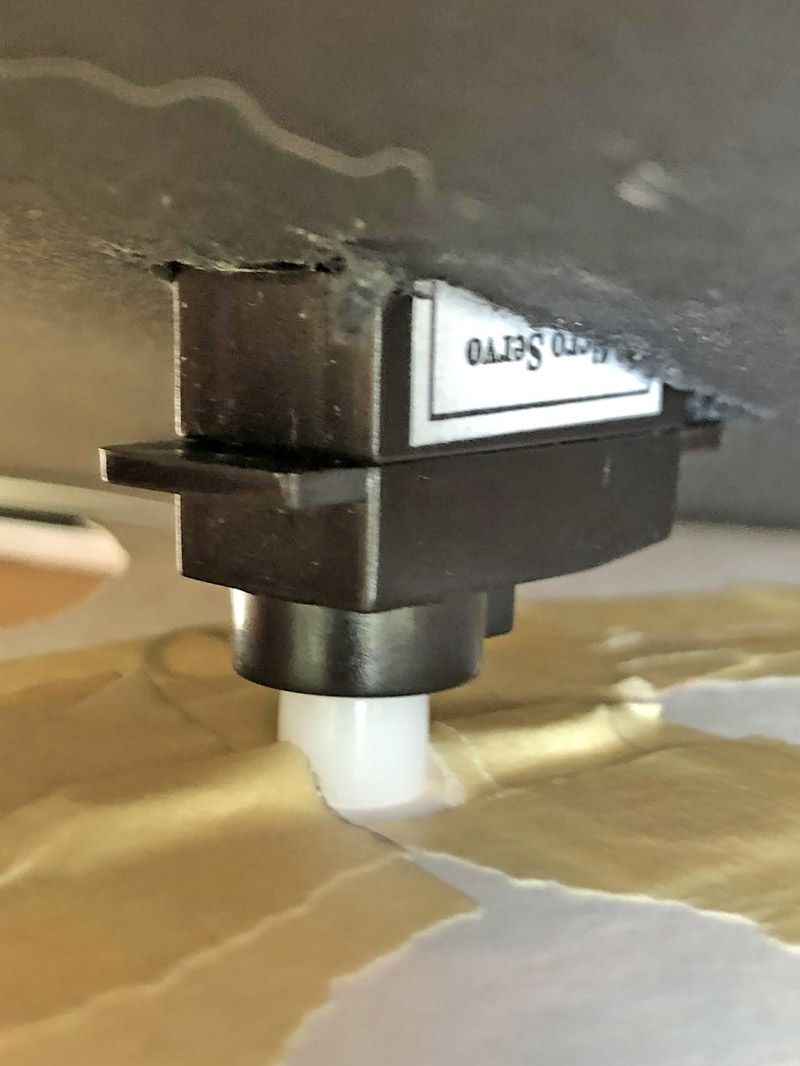
- Have students trace the bottom of the servo motor onto the foamboard where the stomach will go and cut it out carefully using a pair of scissors. Next, they should check that the servo will sit in the hole without falling through. The servo motor has a “lip” with screw holes for mounting, but we will just be using tape to secure it. This lip should sit against the foamboard and not fall through. This does mean the Stomach cutout will not sit perfectly flush. Remind students of this. See Fig 3 for reference.

- Now they are ready to start wiring. This is a step that can easily go wrong, so make sure they are taking their time. They will place the LEDs in the holes, and use masking/clear tape to hold the LEDs in. Do not let them use glue. Once the LEDs are in, they should flip it over to the front side (where the LEDs are poking through) and tape down their paper cutouts. The stomach cutout needs to be taped to the “horn” of the servo. See Fig 3 for reference.
- Lastly, attach three jumper wires to the end of the servo motor, trying to match the colors. See Fig 4 for reference. Now we are ready to attach things to the Arduino!

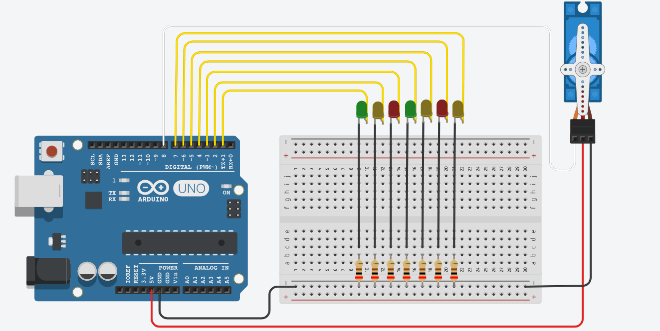
- Show the students Figure 5 for what to attach where. The 2 long legs of the LEDs for the mouth should attach to pins 1 and 2 of the SparkFun RedBoard, respectively. The long leg of the LED for the stomach should attach to pin 3 of the RedBoard and the long legs of the LEDs for the pancreas and gallbladder/liver should attach to pins 4, 5, 6 and 7.

- The short legs of all LEDs should be wired into separate rows with one leg of a 330ohm resistor on the breadboard. The other leg of the resistors should be placed into the blue column of the breadboard.
- The last thing to wire is the Servo motor! The white jumper wire should go into pin 9 of the SparkFun RedBoard. The red wire should go into the 5V pin of the RedBoard and the black wire can either go into a GND pin on the RedBoard or the blue column of the Breadboard. See Fig 5 for reference.
- Lastly, they need to connect a jumper wire from the blue column of the Breadboard (that has all the resistors in it) to a GND pin of the SparkFun RedBoard.
- Next, they should check their wiring with you. Look for all the negative colored wires going into the Breadboard and all the positive colored wires going to the Arduino.
Class 4
- Lastly, it is time for them to code their display. This is up to you how much code you want to give them. I recommend giving them the handout - “Starter code for digestive system display” which will show them how to blink the mouth LEDs three times.
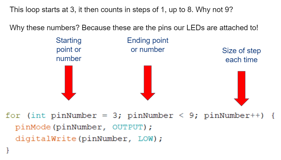
- This uses a for loop. If students are not familiar with a for loop, this is a great time to discuss it. The basic layout of a for loop is in Fig 6.
- Students can also just copy and paste the code to flash more LEDs at different times, but they must figure out how to make a servo move!
- The servo code will be difficult. I recommend you show the students how to use a for loop to make a servo move. You can pull this from the master code file. Have them use a delay of 50ms. If it is a very small delay like 5ms, the servo will not have time to finish moving before the next movement starts. It will look like the servo doesn't move at all.
Figures
|
Fig 1
Correct way to wire an LED using the NASA Splice. Note that mine is not perfect (there are gaps between loops and I did not trim the ends and there are not at least 3 turns)
This is okay - students don’t need perfect splices. Also note the semi flat edge on the right side of the LED. This corresponds with the negative leg, the short leg, of the LED. If you are not sure if they wired their wires correctly, look for this flat edge to indicate which leg is the negative.
|
|
|
Fig 2
Organs laid out and holes for LEDs marked and punched through. Their diagram should resemble something like this.
|
 |
|
Fig 3
Close up of the servo attached to the stomach cutout using tape. Also notice that the lip of the servo is larger than the hole it sits in.
|
 |
|
Fig 4
Close up of connecting jumper wires to the Servo. It seems like you may be harming it but make sure the jumper wires are pushed in firmly.
|
 |
|
Fig 5
Circuit diagram of the entire display. Note the color codes, black is negative, yellow is positive.
|
 |
|
Fig 6
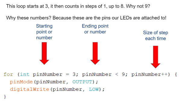
A for loop is a way to tell the Arduino to do something a certain number of times. In this example, the Arduino will count from 3 to 8 (because when i=9 the loop is no longer true and it exits). Inside of the for loop it turns any LED attached to pins 3-8 off and declares them as outputs.
|
 |
Troubleshooting Tips:
- Wiring their LEDs too quickly can lead to connections that are not tight - have them check that this connection is not loose.
- If their LEDs aren’t lighting up correctly, check if they followed the color code conventions where their long legs are attached to the negative colored wire and vice versa.
- Not following the circuit diagram - if their LEDs are tight and their color coding is correct, check that they’ve plugged the right LEDs into the right pins on the RedBoard.
- Wire management is a huge issue here to keep things working. If their wires are a mess, they may unplug from the Arduino whenever it moves. I recommend having them gather all the negative wires and using a strip of tape about 4” to keep them bundled. I personally bundled my LED positives too but in groups by what lights up when.
- i.e. The two mouth LED positive wires were taped together, the 4 that light up for the pancreas and gallbladders/liver were taped together.
- The code may present many problems for them. For students that are struggling with the order and timing - have them write out on paper what LEDs should be blinking at the same time and what should come after that. You may also suggest for them to think how many LEDs should be blinking at the same time when the food travels down. This method called “human coding” is a way that many programmers use to write out what they want to happen, and then they can go step by step through writing that code for each section.
Going Further: There are many ways to take this activity further! Currently, the LEDs only light up to show what molecules are broken down in which locations. There is no indication of what enzymes are present and we stop short of talking about the body absorbing nutrients in the small intestine.
- Students can research the different enzymes released and label the LEDs with their enzymes.
- Students can research what is the stimulus that activates the release of these enzymes and represent this stimulus with a neutral white or blue LED in the system.
- Students can incorporate a button to provoke the start of the system instead of it just looping constantly.
- Students can incorporate three separate buttons - one for each molecule that only lights up the organs that help process these molecules.


.jpg)
