
Activity Name:
Rainbow Mixing with Arduino
Grade Level:
It is targeted for grade 7, but could work for grades 6 to 12.
Time Required:
50 minutes
Expendable Cost:
$0
Group Size:
2
Subject area:
computer science
Summary:
In this exercise, students learn about Red Green Blue (RGB) LEDs and execute simple logical if statements to create a button controlled color mixer using Arduino. When the red button is pressed, the LED will shine red, when the green button is pressed the LED will shine green, and when the blue button is pressed, the LED will shine blue. When two buttons are pressed at the same time, a mix of the two colors will shine. (e.x. pressing the red and blue button at the same time will result in a purple LED.) When all three are pressed, the LED shines a mix of all three colors (white).
Keywords:
LED, Arduino, Color, RGB, Optics, Light, Logic, Electronics, Programming, Engineering
Educational Standards:
ISTE
NGSS
Prerequisite Knowledge:
Have students complete the following projects from the SparkFun Inventor’s Kit for background on using the components used in this project:
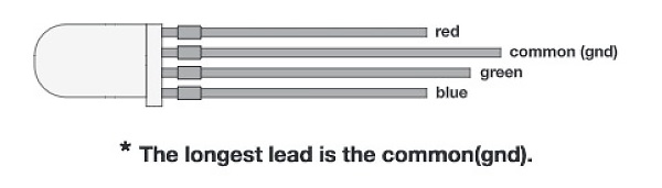
RGB LED: This is essentially three LEDs in one. A red, green, and blue LED are housed within a normal LED housing. Each internal LED shares the same ground leg, resulting in four total legs. To turn one color on, connect the common ground to ground and the desired color to power. Powering multiple colors will result in a blending color, as the illumination from the multiple colors blend together. These LEDs will act as OUTPUTS in our program.
Push buttons: Push buttons are simple circuit switches that close a circuit when pressed, allowing electricity to flow through it. This circuit uses three push buttons: one each of red, green and blue to turn on the corresponding LEDs. These push buttons will act as INPUTS into our program.
Light Color Mixing vs Paint Color Mixing: Mixing light colors is different than mixing paint colors. When mixing paint, the primary colors are red, yellow and blue. Combining these colors results in secondary colors of orange, green and purple.
However, when mixing light, the primary colors are red, green and blue (the RGB of an RGB LED). When mixing light, red + green = yellow, red + blue = magenta, blue + green = cyan and red + green + blue = white.
Learning Objectives:
After this activity, students will be able to:
Materials List:
Each group will need the following materials:
-plus-
-OR-
Introduction / Motivation:
Today, we're going to explore color mixing with light. Color mixing with light is different from mixing paint colors. Can anyone tell me the primary colors of paint? (Correct answer: red, blue and yellow.) Great, now what about the primary colors for light? (Correct answer: red, green and blue.) Now you may have noticed that the colors are different. While red and blue are both considered primary colors for paint and light, when mixing paint, yellow is a primary color, and when mixing light green is a primary color instead.
So, what does that mean for color mixing? As you know, when you mix primary paint colors, you are able to create the secondary colors of orange, purple and green. The goal of today's lesson is to find out what happens when you mix different light colors, how they combine to create secondary colors of light and exactly what those secondary colors are.
Procedure:
Before the Activity
With the Students
First let’s take a look at the hardware set up:
| Pin | Component | Type |
| 9 | Red LED lead | PMW pin, can digital or analogwrite to control the LED |
| 10 | Green LED lead | PMW pin, can digital or analog write to control the LED |
| 11 | Blue LED lead | PMW pin, can digital or analog write to control the LED |
| 2 | Red push button | Digital, will read button presses |
| 4 | Green push button | Digital, will read button presses |
| 7 | Blue push button | Digital, will read button presses |
| 5V | Power rail | |
| GND | Ground rail |

Now the code. The code is commented so that students can easily get the functionality working right away and can connect what is happening and where. Included in the code are a couple of concept questions that explore the use of if, while, and do while statements. This is a great opportunity to have students predict the changes, then implement them to see what happens to the LED, so they can actively think about what the code means rather than just copy paste it.
//first initialize all pins
//these are the pins connected to the buttons
const int RedButton = 2;
const int GreenButton = 4;
const int BlueButton = 7;
//these are the pins connected to each RGB LED lead, respectively
const int RedLED = 9;
const int GreenLED = 10;
const int BlueLED = 11;
//ButtonState will send a reading if the button is pressed or unpressed, this will be important in having the change of state of the button execute a change of state in the LED.
//This variable will change, so we just initialize it to zero as a starting point.
int ButtonStateR = 0;
int ButtonStateG = 0;
int ButtonStateB = 0;
void setup() {
//everything under void setup executes once - we use it configure
//the pins we use into certain modes (input or output)
//and execute any code we want to run only once (for example, test code to make sure your RGB LED is functional)
pinMode(RedButton, INPUT);
pinMode(GreenButton, INPUT);
pinMode(BlueButton, INPUT);
pinMode(RedLED, OUTPUT);
pinMode(GreenLED, OUTPUT);
pinMode(BlueLED, OUTPUT);
//cycle through the RGB colors to make sure the LED is working
//tells the microcontroller to turn on the LED for 100ms
digitalWrite(RedLED, HIGH);
delay(100);
//tells the microcontroller to turn off the LED for 50ms
digitalWrite(RedLED, LOW);
delay(50);
digitalWrite(GreenLED, HIGH);
delay(100);
digitalWrite(GreenLED, LOW);
delay(50);
digitalWrite(BlueLED, HIGH);
delay(100);
digitalWrite(BlueLED, LOW);
delay(50);
//sets up serial communication between the board and the serial port
//
Serial.begin(9600);
//R
void loop() {
// set up the ButtonState readers for each LED.
// digitalRead will read the state of each pin every time this part of the code loops, allowing us to determine if the button is being pressed or not.
// Question for students: why does this chunk of code need to be in the void loop part?
ButtonStateR = digitalRead(RedButton);
delay(5);
ButtonStateG = digitalRead(GreenButton);
delay(5);
ButtonStateB = digitalRead(BlueButton);
delay(5);
// Question for students: what do you think will happen if you change the if statements to while
statements?
// Why are we turning the LED HIGH when the ButtonSate is low?
// This is because of the pull-up resistors used in the circuit.
// What are pull up resistors? Read below for more information:
// With a pull-up resistor, the input pin will read a high state
// when the button is not pressed. In other words, a small amount
// of current is flowing between VCC and the input pin (not to ground),
// thus the input pin reads close to VCC. When the button is pressed, it
// connects the input pin directly to ground. The current flows through
// the resistor to ground, thus the input pin reads a low state. Keep in mind,
// while the resistor wasn’t there, your button would connect VCC to ground,
// which is very bad and is also known as a short.
if (ButtonStateR == LOW) {
Serial.println("red button pressed");
digitalWrite(RedLED, HIGH);
delay(5);
}
else
{
digitalWrite(RedLED, LOW);
delay(5);
}
// Why use the Serial.println?
// So we can debug our circuit - if the serial monitor isn't displaying a button press when there has been one,
// we know something in the circuit must be wrong.
if (ButtonStateG == LOW) {
Serial.println("green button pressed");
digitalWrite(GreenLED, HIGH);
delay(5);
}
else
{
digitalWrite(GreenLED, LOW);
delay(5);
}
if (digitalRead(BlueButton) == LOW) {
Serial.println("blue button pressed");
digitalWrite(BlueLED, HIGH);
delay(5);
}
else {
digitalWrite(BlueLED, LOW);
delay(5);
}
}
Programming questions to ask yourself
Q: What do you think will happen when you comment out the else statement? What happened when you did?
A: Without the else, there is no condition for when a certain button is not being pressed after it has initially been pressed. The corresponding LED will just remain on, and any additional button presses from the other two colors will turn on their corresponding colors as well. This will still result in color mixing, but you won’t be able to take out a color once its button has been pressed.
Q: What do you think will happen when you change the if statements to while loops? What happened when you did?
A: The first button that is pressed turns on it’s corresponding LED, and that’s it. No additional button presses will turn on their corresponding LEDs. Why? Because we used a while loop, the code is now stuck in that loop unless we give it a condition that can break it out of the loop (like, say break out of the loop after 1 second). Students may think the ButtonState code will be running continuously, but this code runs “line by line” sequentially. So if a while loop is used, it needs a condition to break it, otherwise it will run forever
Q: Why are we turning the LED HIGH when the ButtonSate is low?
A: This is because of the pull-up resistors used in the circuit. With a pull-up resistor, the input pin will read a high (on) state when the button is not pressed. In other words, a small amount of current is flowing between VCC and the input pin (not to ground). The input pin reads this as connected to VCC, or HIGH. When the button is pressed, it connects the input pin directly to ground. The current flows through the resistor to ground, pulling the reading to LOW. Keep in mind, while the resistor wasn’t there, your button would connect VCC to ground, which is also known as a short. The resistor gives just enough resistance to the current to keep that from happening.
Troubleshooting Tips:
Pushing a button turns the LED the wrong color.
Things to check:
A color isn’t lighting up
Things to check:
Nothing works!
Things to check:
Going Further:


