
Activity Name:
Won’t you take me to...Coding Town!
Grade Level:
This project is designed for grade 8 but could work for grades 5-12.
Time Required:
60 minutes
Expendable Cost:
None! Everything is reusable
Group Size:
2 is preferred but this can be done solo if the students are advanced.
Subject area:
Problem solving, Number and Operations, Science and Technology
Summary:
Students are learning how the stage lights at concerts work and are timed to fit musical rhythms. The blinking of a light to replicate music is based in communication techniques of ships, called a signal lamp, where a version of Morse code is used. An iconic song to use for this task is the hook of Funky Town. With only three distinct tones, and relatively regular beats, students convert musical scores to light sequences. Beats per minute are converted, using math, and problem solving must be used to get the sequence just right. This is also a great introduction to how coding is used in real life, as light sequencing is used not at concerts but also in areas such as Christmas Lights!
Keywords:
Light Waves, Arduino Music, Timing Lights, Coding LEDs
Educational Standards:
ISTE
NGSS
Pre-Requisite Knowledge:
Basic Arduino coding (how to turn on and off an LED) is desired as this lesson focuses more on using delays to change the timing of light sequences.
Learning Objectives:
Materials List:
**All required parts can be found in the SparkFun Inventor's Kit v4.0 or 4.1**
Introduction / Motivation:
How many have ever been to a concert? How many have ever seen Christmas lights? (Almost all hands should have gone up by now.) What do these two have in common? (You’ll get a range of answers but doubtful that many will talk about the lights) The answer may surprise you - it’s the lights! Concerts and Christmas lights are often controlled by some kind of timing mechanism to create these fantastic effects that enhance the experience. The bigger/more popular the band, the more amazing the light effects! Just imagine the Super Bowl. It may surprise you, but lights and sound have a lot in common. For instance, they both are waves! They also are both used to communicate information. Can anybody give me an example of how lights are used to communicate information? (Possible answers: Open signs, Morse Code, Internet/Fiber Optic) All of those are great answers! Light is used to communicate information, and Morse code is a very simple system that consists of dots and dashes but on ships, they used a Signal Lamp (show image of signal lamp on the screen) which is either on or off to communicate.

Timing is everything here. So today we will be learning how to blink our own LEDs to the beat of a song - but instead of just 1, we will use 3!
Procedure:
Background
Please make sure you have done at least 1 or 2 Arduino lessons with your class beforehand. Ideally Project 1A: Blinking an LED and Project 2B: Digital Trumpet from the SparkFun SIK 4.1 Guide. If you really want students to excel, completing the entirety of Project 2 from the SparkFun SIK 4.1 will greatly aid them. While the code is relatively simple, the editing can get tricky when we are dealing with timing. Make sure to review:
Before the Activity
With the Students
First, let’s take a look at the song Funky Town. It has a hook that is a very simple beat, and consists of 5 notes, which we will simplify to three because they are similar enough. (Good time to play the hook of Funky Town for the students to hear it and keep playing it as you write the sequence out on the board with students help.) Now let’s try to determine the order of these tones. (Draw a 3 rows x 10 columns grid on the board. Next to each row write the words “high, medium and low” in descending order down the grid. It should look like below)
| High | ||||||||||
| Medium | ||||||||||
| Low |
Alright let’s try to fill this chart in just to determine the order of tones and subsequently, lights! (Now begin to play the song and ask students to help you fill in the order of tones based on is the tone higher or lower than the previous one? Eventually the grid should look like below.)
| High | x | |||||||||
| Medium | x | x | x | x | x | |||||
| Low | x | x | x | x |
So, let’s talk about our process for a moment. Engineering has many disciplines but all of them are focused on solving problems with some type of process. This process usually begins with establishing what we do know, and what we do not know. In this case, we know the tones and do not have to write the song ourselves. We also know that we wish to break them down into some type of sequence. So our process is to try and chart out, over time, the sequence of notes, similar to sheet music! Next, we must figure out how to turn this series of Xs into flashing LEDs. But before we code our LEDs, we need to set up our circuit!
How many LEDs will we need? (Answer should be 3! Direct them to look at how many tones there are in the grid) And how can we use our LEDs to distinguish between tones besides just when each one flashes? (Answers may range between number or speed but we are looking for color!) Yes! Color!
Different colors should correspond to different tones. The next thing about Engineering is something called standards. When communicating information, we must all agree on a system of symbols. For instance, green typically means go and red means stop. So what color would we like our high note to be? (Any answer is fine as long as the class agrees. Do this for the next two LEDs, making sure there are no two of the same color) So now the grid should look like below:
| (color) | High | x | |||||||||
| (color) | Medium | x | x | x | x | x | |||||
| (color) | Low | x | x | x | x |
Okay, let’s try to set up our circuit! (Familiarity with circuits will help a lot here. Otherwise this will take an entire class.)
This is our next problem and our process for this will be to first write out the code to get one LED to flash/blink. And then we will replicate it how many times? (Looking for the answer of replicate it 9 more times for a total of 10 blinks)
Setting Up the Circuit:
Step 1: Take the USB cord and plug it into your computer but not into the SparkFun RedBoard yet!
Step 2: Plug one end of a jumper wire into the 5v slot on the SparkFun RedBoard, and the other end into the positive red column on the breadboard.
Step 3: Take a different jumper wire and plug one end into the GND pin below the 5v pin on the SparkFun RedBoard and connect the other end of the wire to the blue negative column next to the previous wire.
Step 4: Take three new jumper wires and plug one end of each into Digital pins 3, 4 and 5 respectively on the SparkFun RedBoard and plug the other ends into three different rows on the breadboard.
Step 5: Take three, 200 ohm resistors and plug each one into the row below the three previous wires. One end of the resistor goes in the row below the wire, and the other end connects to the negative blue column that contains the GND wire, as previously mentioned.
Step 6: For the LEDs, take note of the short(negative) and long(positive) ends. The long end needs to be plugged into the same row as one of the jumper wires and the shorter end needs to be plugged into the row directly below it, in line with the 200 ohm resistor. Repeat this process for the next two LEDs.
Step 7 : Take a new wire and plug one end into the red, positive column of the breadboard and the other into any row on the breadboard that is not already used by other wires or components.
Step 8: Take the 10k resistor and plug 1 end into the negative black column and the other end two rows below the previous wire of step seven. For example, if the previous wire was plugged into row 23, the resistor should be plugged into row 25 to account for the width of the button.
Step 9: Now, take one more jumper wire and plug one end into pin 8 on the SparkFun RedBoard and the other end into the same row as the 10k resistor.
Step 10: Lastly, take the button and plug one foot into the same row as the 10k resistor and the other foot into the same row as jumper wire that is only connected to the breadboard from step 7.
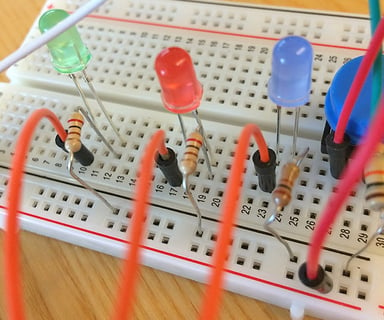
Please see figures below for examples on how to setup LEDs, resistors and the button.
|
Fig 1 The three LEDs in line with their resistors. Short leg of the LED must be in the same row as the resistor. The long leg is in the same row as the wire coming from the Arduino. |
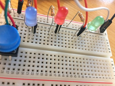
 |
|
Fig 2 ( Different view )The three LEDs in line with their resistors. Short leg of the LED must be in the same row as the resistor. The long leg is in the same row as the wire coming from the Arduino. |
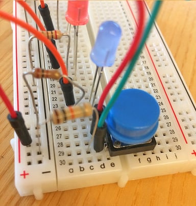
 |
|
Fig 3 The button is setup with the resistor and 2 wires. The red wire goes to the 5V line of the breadboard and the green wire goes to pin 8 of the Arduino. |
 |
|
Fig 4 Full circuit diagram for those who may be struggling with written instructions! |
 |
Now that we have our circuit setup, let’s add some code! (Hand out the Starter Code with the code to blink one LED) You will notice that the handout has enough code to turn on and off two LEDs and that the name of the LED is “mediumTone” which corresponds with the grid above. Now you must write the code for the other 8 grid squares or sequence. I suggest you do this first, then go back and change what is inside the digitalWrite section of code for each “tone”. Refer to the grid on the board. (Students should upload the code after adding each new block of code to blink the next LED, instead of writing all of the code and uploading it at the end.) This is an example of process in Engineering. Instead of building an entire car and then testing all of the parts at once, you test each part that is built. That way if there is an error or problem, you know where it is coming from - the last part that you added!
Now students should check off that each LED blinks the appropriate number of times. It is okay if the time in-between blinks is not perfect but they should blink in the correct order.
Next students should work on altering the delay variables in the beginning of the code. Instead of having to change each and every delay in the void loop section, encourage students to change the value corresponding to the variables above void setup. For each new section of code they should pick one of the variables to use for the delays. You may need to write these up on the board for them to understand.
Troubleshooting Tips:
Students may struggle to understand how to turn a sequence of Xs into flashing LEDs if they haven’t seen this before. Be sure to provide visual cues to get them to understand how to work with sequences. An easy way is a game of Simon Says. (Simon may put their foot down but players are not to do anything unless specifically instructed to) so the students must be very careful in their instructions to the computer.
The idea of timing “rests” (which is the absence of a tone) is also difficult for students. This is why the code given to them has three variables for different rests. These can be seen in the delay code sections. Strongly encourage students to use these variables and only change the value of the variable above the void setup, not in the void loop.
Going Further:
Technically the hook of funky town has 5 different tones. Students may look up the sheet music to create a new grid of sequencing times for themselves. Then by adding two LEDs, they can create the true sequence of lights.

.jpg)
